matlab的fdatool是好东西,不过很多人不知道该怎么使用它生成的C头文件。
趁着放假有时间,摸索了几天,终于搞定。希望阿莫给条裤子。
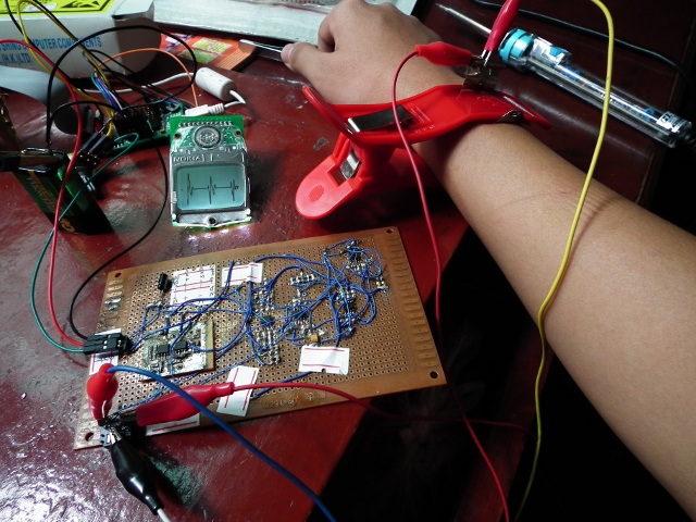
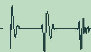
该程序已经用于心电采集实验
导联aVF,带宽1-25Hz

实验过程中图片 (原文件名 SCF6003.JPG) SCF6003.JPG)

液晶截图 (原文件名:aVF_LCD.jpg)
不多说,切入正题
这里有个fdatool设计的IIR高通滤波器,采样率400Hz时截止频率1Hz。
设计定型之后,要做些调整。
以下说明中的英文名词有些可能对不上fdatool界面上的原文,请大家意会吧
第一步:
点击菜单中的Edit->Convert Structure 选择Direct Form I ,SOS,(必须是Direct Form I, II不行)
一般情况下,按照默认设置,fdatool设计都是由二阶部分串联组成的。
这种结构的滤波器稳定性比一个section的要好很多,其他方面的性能也好些。
如果不是的话,点击Convert to second order sections。
这时,滤波器的结构(structure)应该显示为 Direct Form I,second order sections
第二步:
选择quantize filter,精度选择single precision floating point (单精度浮点)
之所以不用定点是因为噪声太大,也不容易稳定。
点击菜单中的Targets -> generate c header ,选择export as:single precision floating point (单精度浮点)
填写变量名称时,把NUM改成IIR_B,DEN改成IIR_A,其他不用动,保存为iir_coefs.h
保存好的文件如下:
//一大堆注释
//然后:
/* General type conversion for MATLAB generated C-code */
#include "tmwtypes.h"
/*
* Expected path to tmwtypes.h
* C:\Program Files\MATLAB\R2010a\extern\include\tmwtypes.h
*/
/*
* Warning - Filter coefficients were truncated to fit specified data type.
* The resulting response may not match generated theoretical response.
* Use the Filter Design & Analysis Tool to design accurate
* single-precision filter coefficients.
*/
#define MWSPT_NSEC 9
const int NL[MWSPT_NSEC] = { 1,3,1,3,1,3,1,3,1 };
const real32_T IIR_B[MWSPT_NSEC][3] = {
{
0.8641357422, 0, 0
},
{
1, -2, 1
},
{
0.9949035645, 0, 0
},
{
1, -1.999938965, 1
},
{
0.9985351563, 0, 0
},
{
1, -1.99987793, 1
},
{
0.9996337891, 0, 0
},
{
1, -1.99987793, 1
},
{
1, 0, 0
}
};
const int DL[MWSPT_NSEC] = { 1,3,1,3,1,3,1,3,1 };
const real32_T IIR_A[MWSPT_NSEC][3] = {
{
1, 0, 0
},
{
1, -1.938049316, 0.9401855469
},
{
1, 0, 0
},
{
1, -1.989501953, 0.9900512695
},
{
1, 0, 0
},
{
1, -1.996887207, 0.9971923828
},
{
1, 0, 0
},
{
1, -1.999084473, 0.9993286133
},
{
1, 0, 0
}
};
第三步:
打开iir_coefs.h把MWSPT_NSEC替换成IIR_NSEC,
NL、DL数组删除掉,real32_T改成float ,
其中有一个#include "twmtypes.h",不要它了,删掉
改完的文件如下:
#define IIR_NSEC 9
//原来叫做MWSPT_NSEC
const float IIR_B[IIR_NSEC][3] = {
//为什么改为float很明显了吧
{
0.8641357422, 0, 0
},
{
1, -2, 1
},
{
0.9949035645, 0, 0
},
{
1, -1.999938965, 1
},
{
0.9985351563, 0, 0
},
{
1, -1.99987793, 1
},
{
0.9996337891, 0, 0
},
{
1, -1.99987793, 1
},
{
1, 0, 0
}
};
const float IIR_A[IIR_NSEC][3] = {
{
1, 0, 0
},
{
1, -1.938049316, 0.9401855469
},
{
1, 0, 0
},
{
1, -1.989501953, 0.9900512695
},
{
1, 0, 0
},
{
1, -1.996887207, 0.9971923828
},
{
1, 0, 0
},
{
1, -1.999084473, 0.9993286133
},
{
1, 0, 0
}
};
保存文件,然后使用以下代码进行滤波
这段代码是根据Direct Form I 2阶IIR滤波的差分方程编写的
a0*y[n] = b0*x[n] + b1*x[n-1] + b2*x[n-2] - a1*y[n-1] -a2*y[n-2];
//iir_filter.c
#include "datatype.h"
#include "iir_filter.h"
#include "iir_coefs.h"
static float y[IIR_NSEC][3];
static float x[IIR_NSEC+1][3];
int16 iir_filter(int16 in)
{
uint16 i;
x[0][0] = in;
for(i=0;i<IIR_NSEC;i++)
{
y[0] =x[0]*IIR_B[0]+x[1]*IIR_B[1]+x[2]*IIR_B[2]-y[1]*IIR_A[1]-y[2]*IIR_A[2];
y[0] /= IIR_A[0];
y[2]=y[1];y[1]=y[0];
x[2]=x[1];x[1]=x[0];
x[i+1][0] = y[0];
}
if( x[IIR_NSEC][0]>32767) x[IIR_NSEC][0]=32767;
if( x[IIR_NSEC][0]<-32768) x[IIR_NSEC][0]=-32768;
return ((int16)x[IIR_NSEC][0]);
}
//复位滤波器
void iir_reset(void)
{
uint16 i,j;
for(i=0;i<IIR_NSEC+1;i++)
{
for(j=0;j<3;j++)
{
x[j]=0;
}
}
for(i=0;i<IIR_NSEC;i++)
{
for(j=0;j<3;j++)
{
y[j]=0;
}
}
}
//iir_filter.h
#ifndef _IIR_FILTER_H__
#define _IIR_FILTER_H__
int16 iir_filter(int16 x);
void iir_reset(void);
#endif
使用方法:
首先写好iir_coefs.h,然后调用iir_filter.c对数据流进行滤波
一个伪代码例子:
while(运行中)
{
保存到SD卡(iir_filter(读取ADC采样值()));
}
这个函数比STM32 DSP库中的函数要好很多,DSP库中的2个IIR滤波函数都不能连续处理数据流。
记得在开始滤波之前重置滤波器
iir_reset();
资料转载于他站、仅供同学学习使用
|