在数字系统设计中,经常涉及到要在某个时钟的上升沿或下降沿进行数据处理,通过自己总结和看别人的程序,发现有好多种方法进行处理,现在我把这几种方法列举一下,大家讨论下他们的优缺点。
背景:假设初始条件A=0,B=0,要在信号A的上升沿将B置为1。
方法1 最简单也是最容易想到的
module Test(rst_n, A, B);
input rst_n;
input A;
output B;
reg B;
always @(posedge A or negedge rst_n)
if(!rst_n)
B <= 1'b0;
else
B <= 1'b1;
endmodule
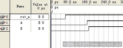
方法1仿真波形 (原文件名:m1.png)
方法2 通过系统时钟
module Test(rst_n,clock, A, B);
input rst_n;
input clock;
input A;
output B;
reg B;
reg A_BUF,A_RISE;
always @(posedge clock or negedge rst_n)
if(!rst_n)
begin
A_BUF <= 1'b0;
A_RISE <= 1'b0;
end
else
begin
A_BUF <= A;
A_RISE <= (~A_BUF) & A;
end
always @ (posedge clock or negedge rst_n)
if(!rst_n)
B <= 1'b0;
else if(A_RISE)
B <= 1'b1;
endmodule
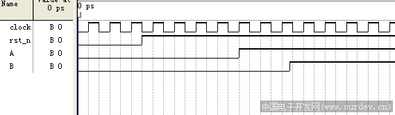
方法2仿真波形 (原文件名:m2.png)
方法3 跟方法2很像,结果却不太一样
module Test(rst_n,clock, A, B);
input rst_n;
input clock;
input A;
output B;
reg B;
reg A_BUF;
always @(posedge clock or negedge rst_n)
if(!rst_n)
begin
A_BUF <= 1'b0;
end
else
begin
A_BUF <= A;
end
wire A_RISE = (~A_BUF) & A;
always @ (posedge clock or negedge rst_n)
if(!rst_n)
B <= 1'b0;
else if(A_RISE)
B <= 1'b1;
endmodule
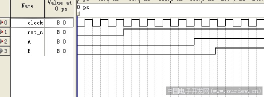
方法3仿真波形 (原文件名:m3.png)
方法4 使用系统时钟
module Test(rst_n,clock, A, B);
input rst_n;
input clock;
input A;
output B;
reg B;
reg[2:0] A_BUF;
always @(posedge clock or negedge rst_n)
if(!rst_n)
begin
A_BUF <= 3'b000;
end
else
begin
A_BUF <= {A_BUF[1:0], A};
end
wire A_RISE = (A_BUF[2:1] == 2'b01);
always @ (posedge clock or negedge rst_n)
if(!rst_n)
B <= 1'b0;
else if(A_RISE)
B <= 1'b1;
endmodule
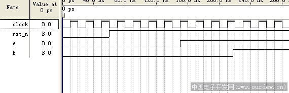
方法4仿真波形 (原文件名:m4.png)
目前我能想到的就这4种了,大家还有什么好的想法不妨一起交流下,呵呵
这些方法都能实现功能,只是反应时间上有区别。根据仿真结果来看,第一种结果最好,延时最短,但就是第一种我见到的用的最少,不知道为什么,这样用有什么缺点么???? |
|
|
|


 发表于 2016-6-17 16:08:38

 收藏
收藏 分享
分享 支持
支持 反对
反对